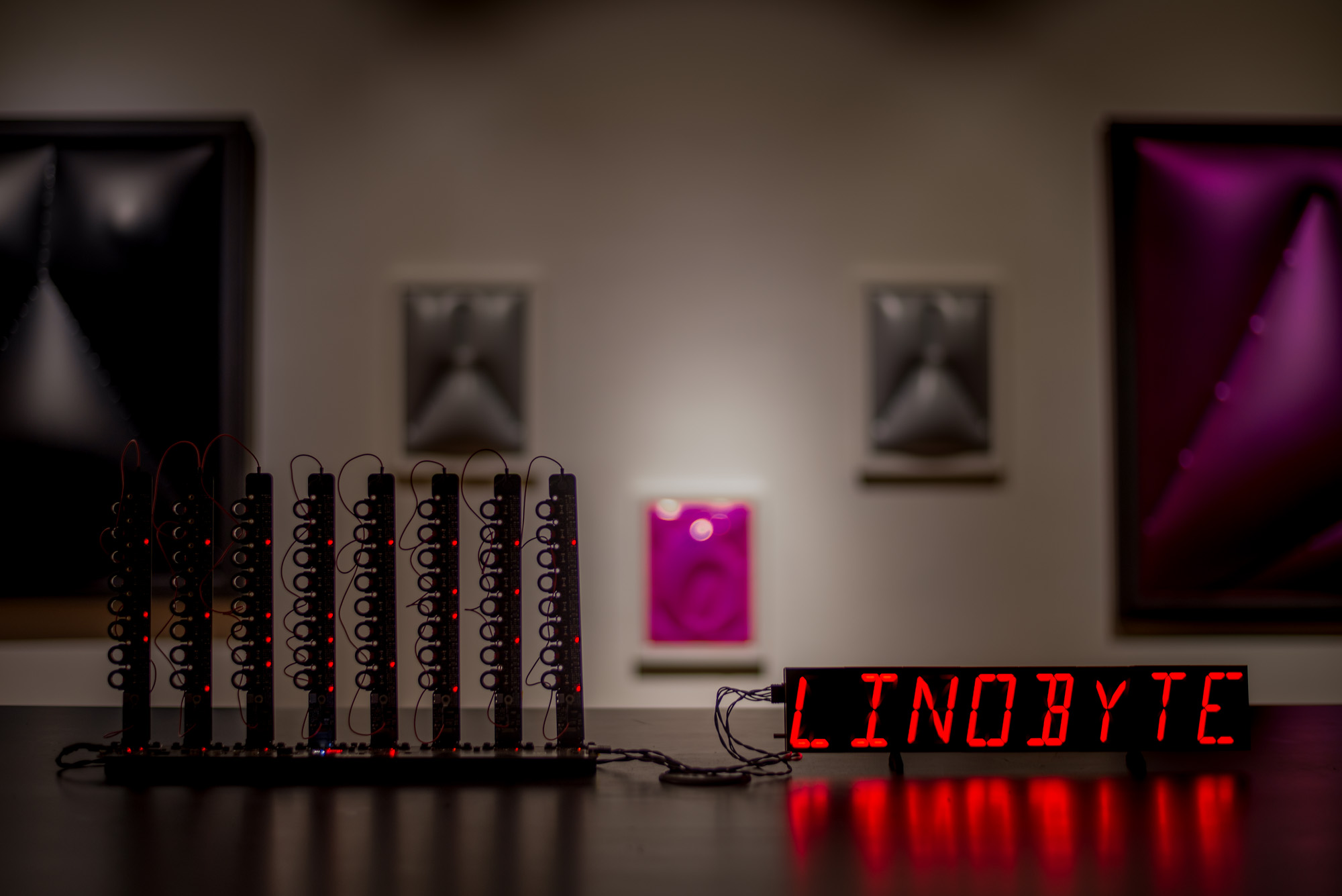
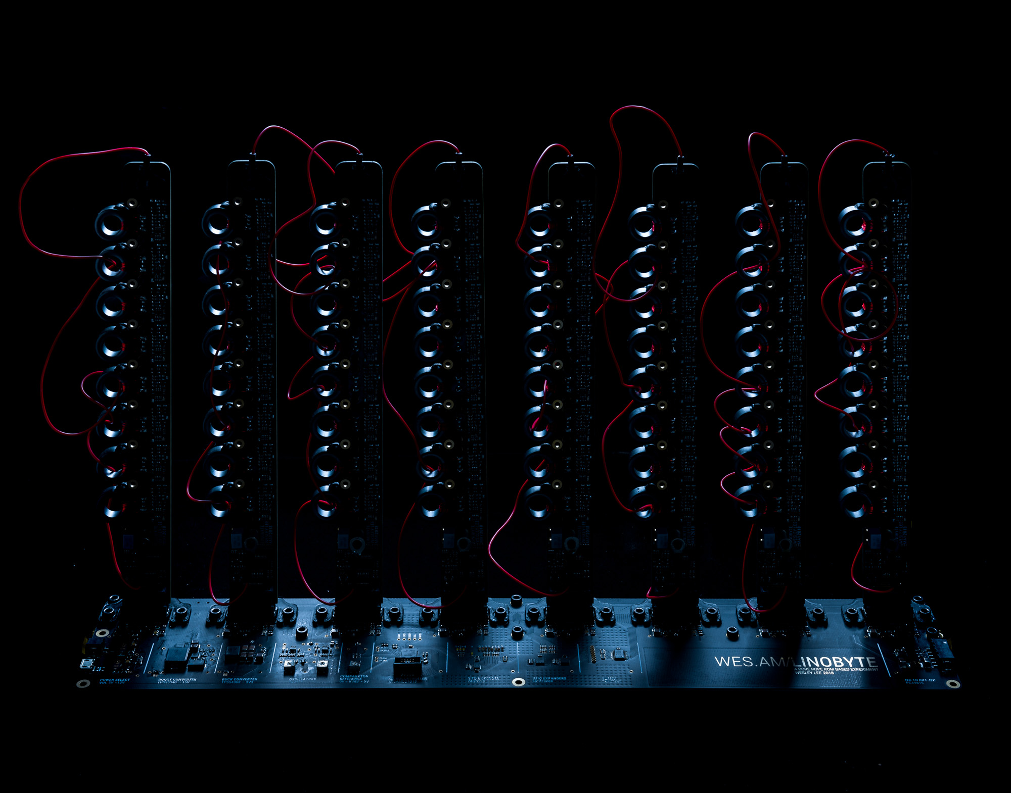
Linobyte
A CORE ROPE ROM EXPERIMENT
Comments / TL;DR:
Linobyte is born from the desire of experimenting with:
- interfaces using magnetic fields
- translating bits, bytes, characters into a visually understandable form
- exploring obsolete/forgotten computer history (people know core RAMs, but not so much core ROMs)
- exploring making ofs as a tool to draw attention to a topic
Technically, I wanted to explore a bit:
- modular systems of boards with multiple interconnects (designing multiple projects of different boards which have to mate electronilcally and mechanically)
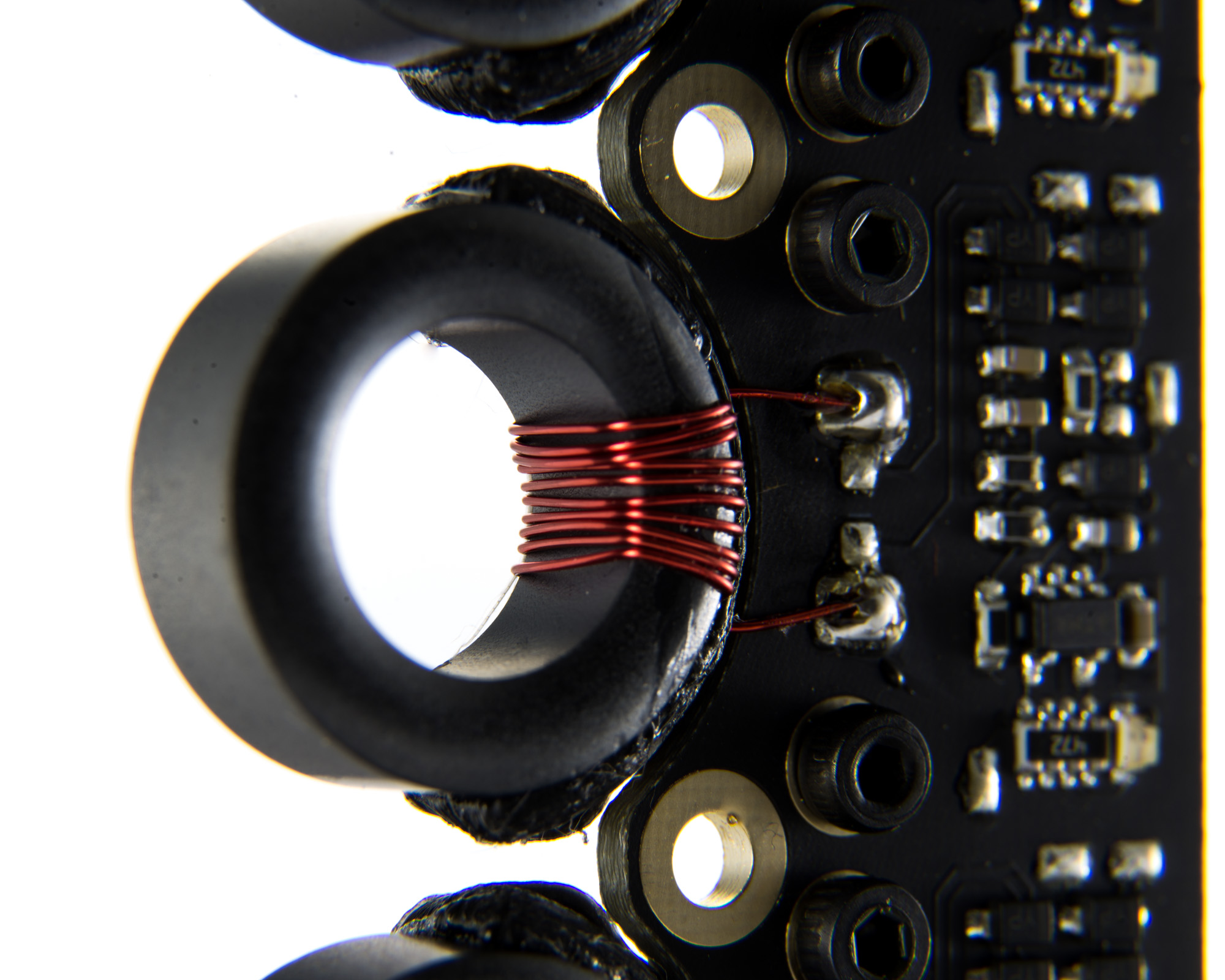
- making DIY transformers (winding, 3D printing)
- assemblying large amounts of components in my workspace at Interface Cultures Linz
- analog circuits (some of which I ended up not using, but still its the start of a process)
I tried to insert these interests on an project that made sense in the context of Interface Cultures, Ars Electronica and Media Archeology Class.
Motivation and Description
As computational devices evolve, more tools and interfaces are built between the user and the machine. This allows us to complete increasingly complex tasks without having to focus so much on understanding the nuances of the machine. While this movement is certainly overall positive, one of the drawbacks is that people no longer learn the fundamental processes and concepts which allow the tool to work. Added to that, by neglecting history, we forget the alternatives of the technologies that we use today - forgotten alternatives that maybe once were the status quo. Understanding of those alternatives would give us a broader view of the pros and cons of what we have today, how they superseded their ancestors and what are their pitfalls - important knowledge for those who design possible futures.
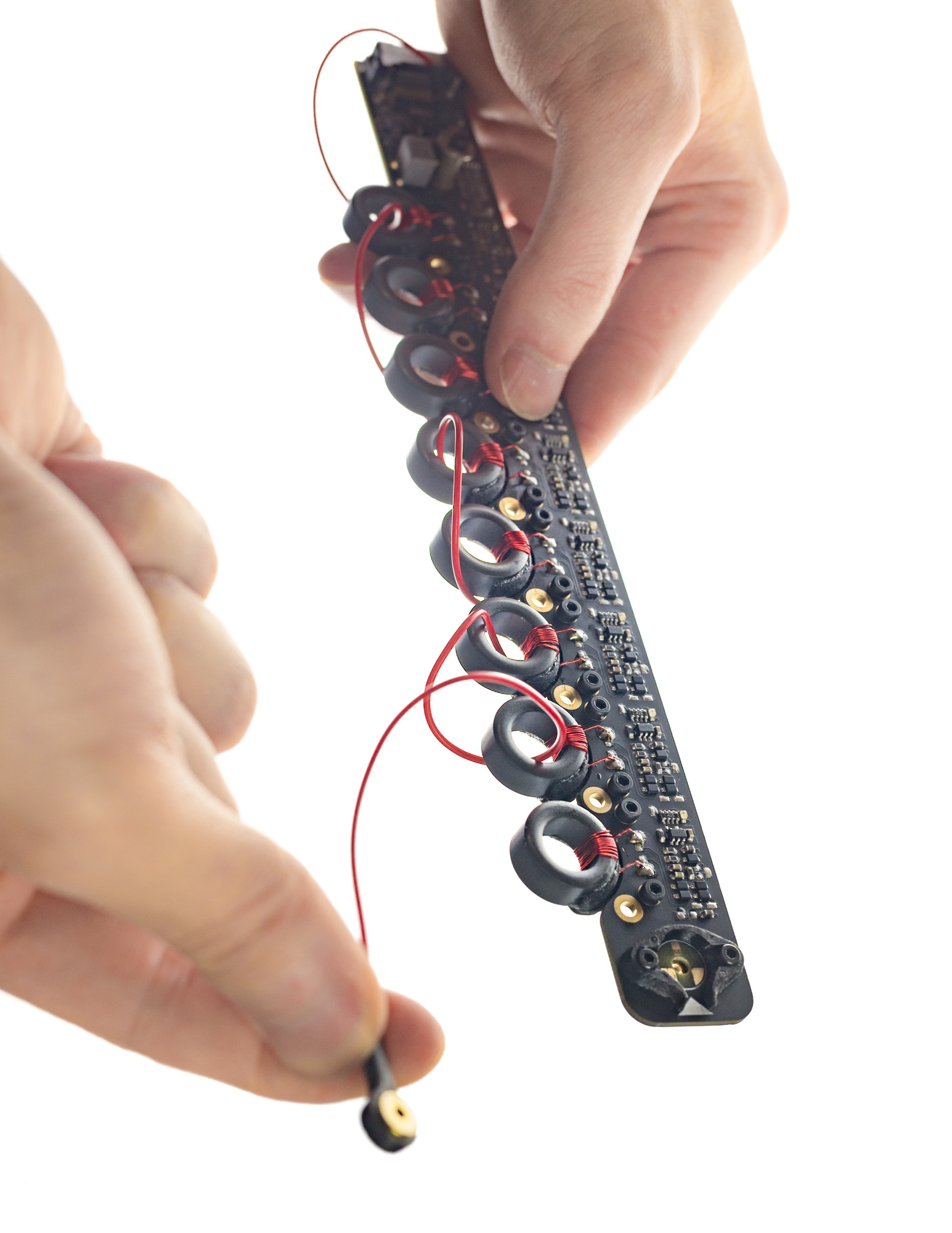
Its with these preocupations in mind that Linobyte came into existence. It conciliates the explanation of how bits, bytes and chars work, with a hands on experience of creating Core Rope ROMs: read-only memories that were written by weaving an enameled copper wire through ferrite cores.
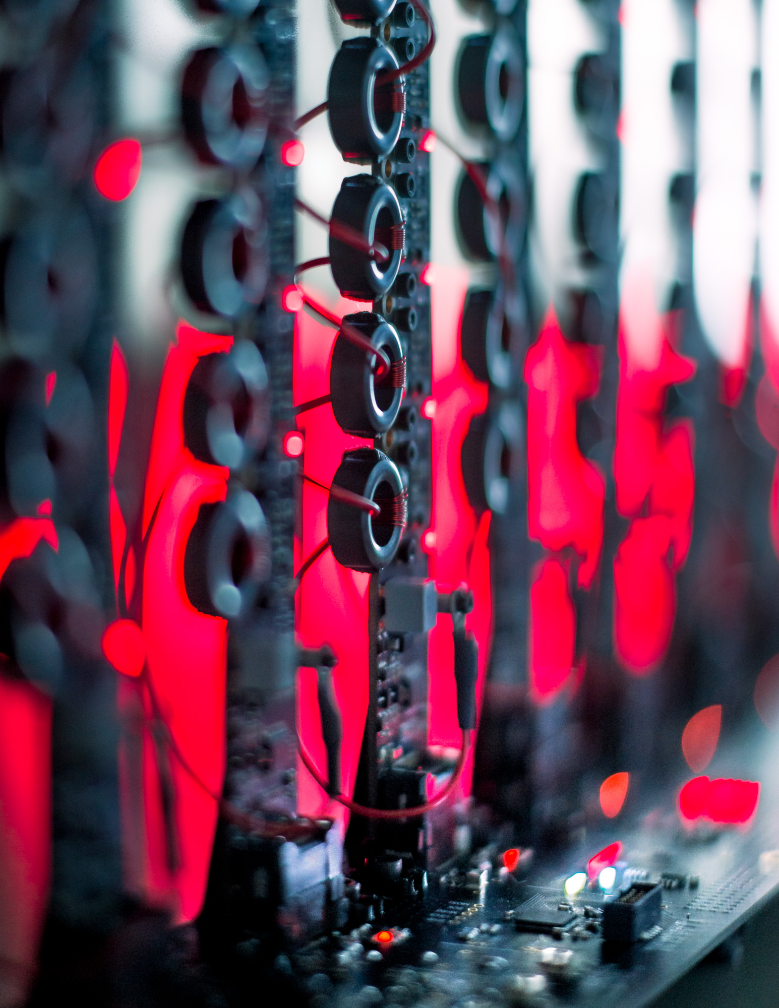
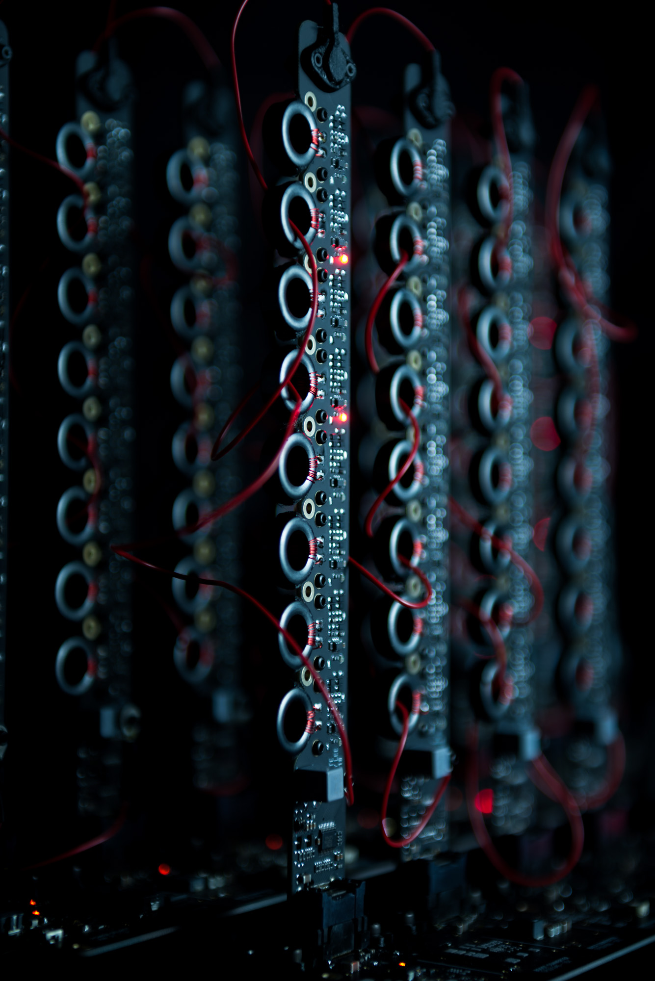
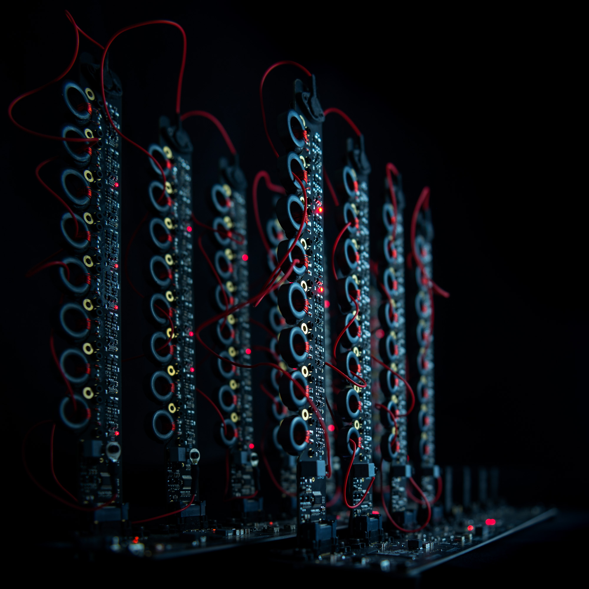
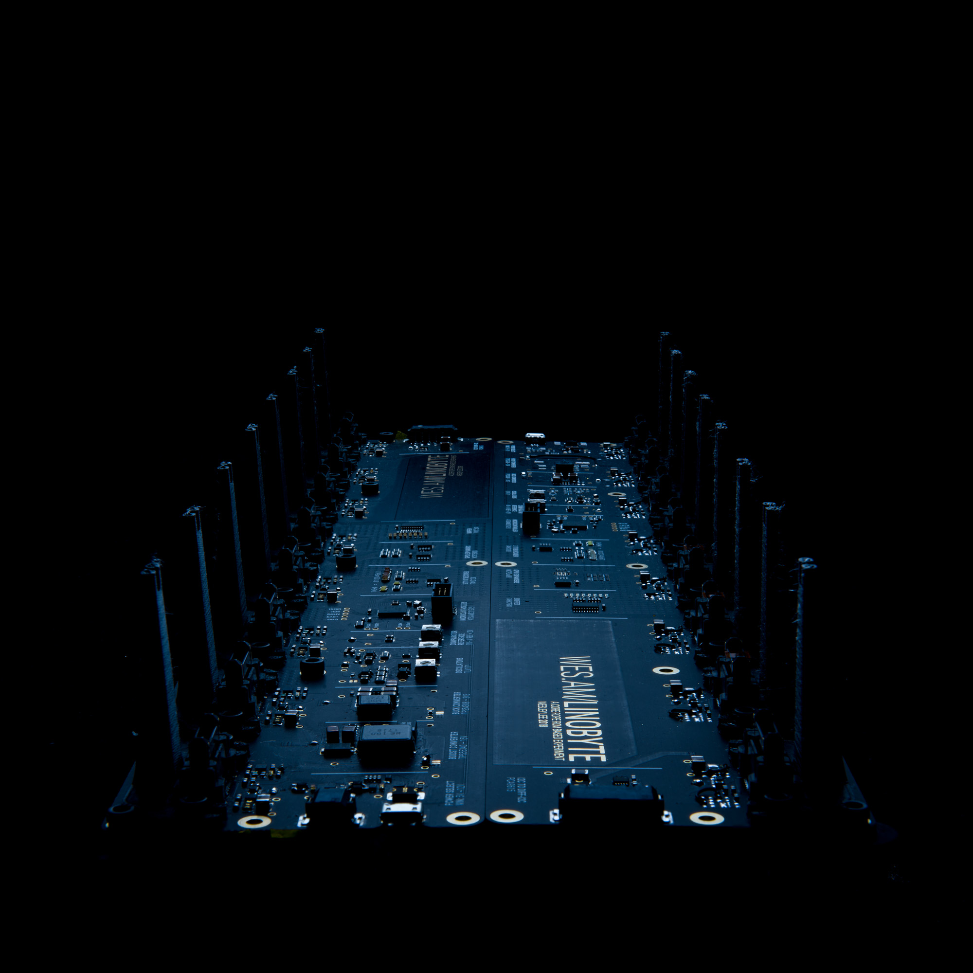
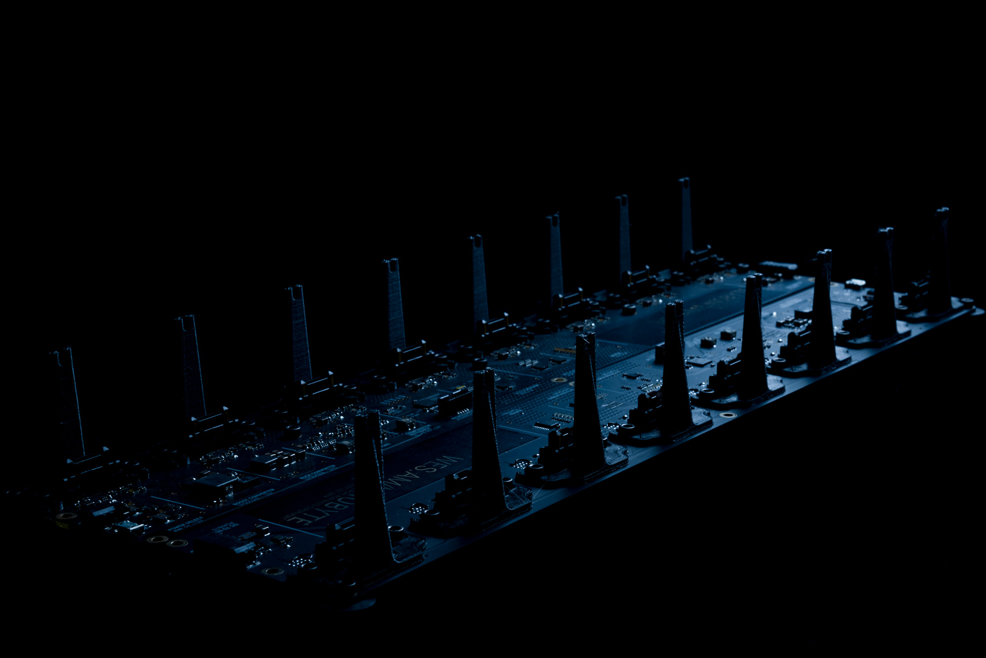
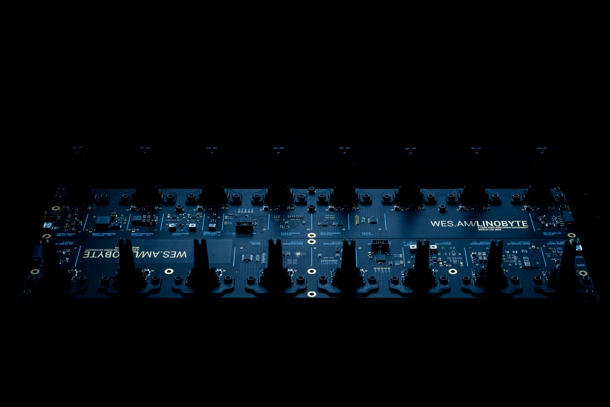
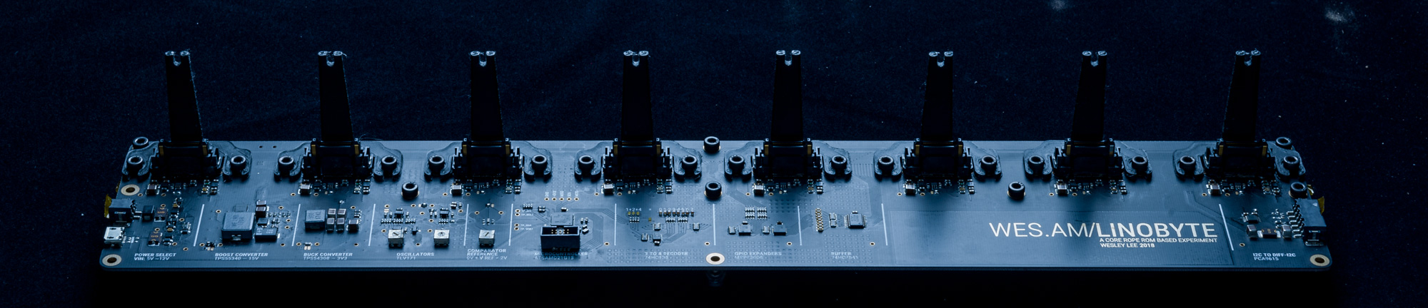
Images:
Excerpts from the Github Repo:
How it works
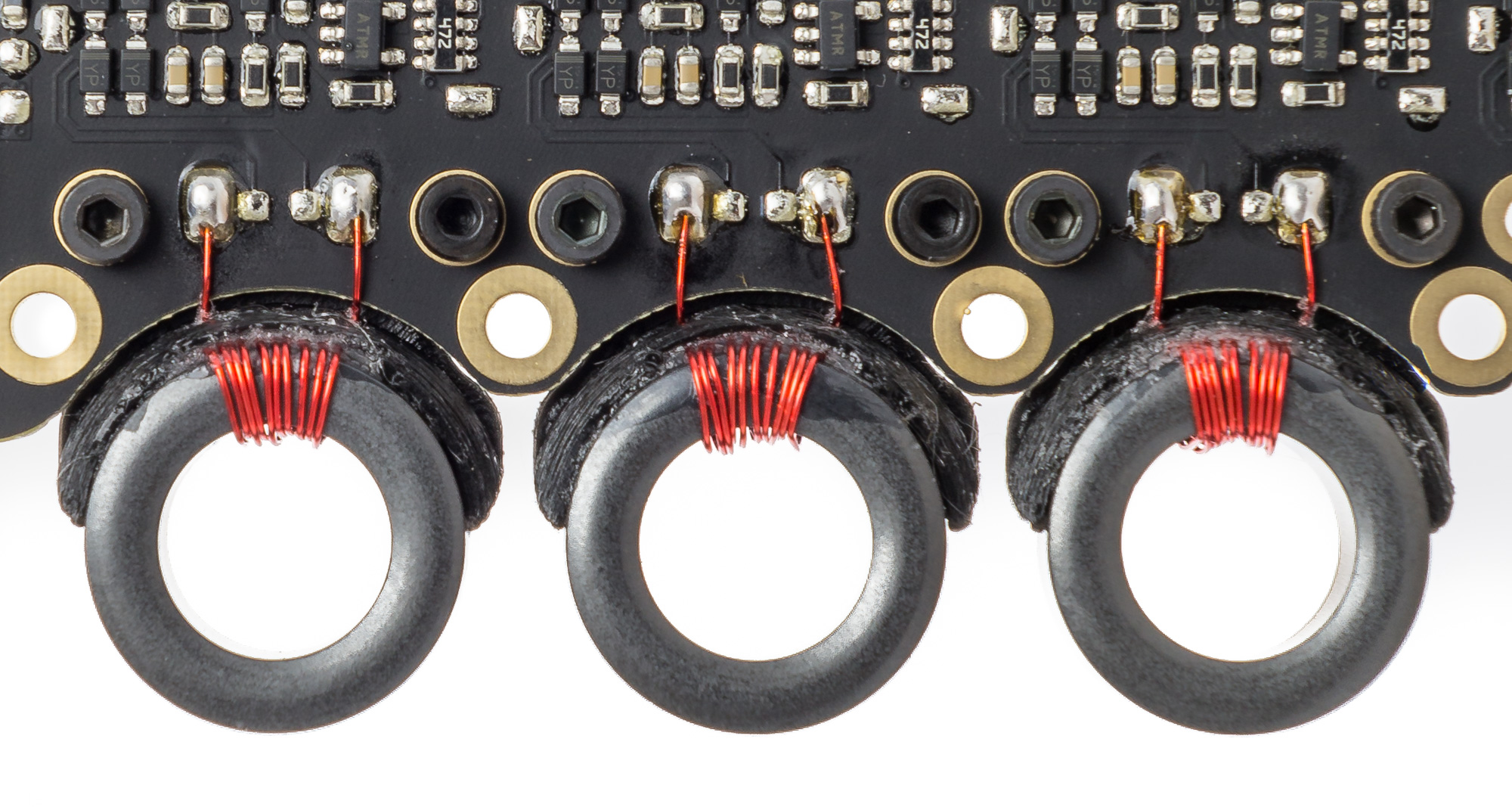
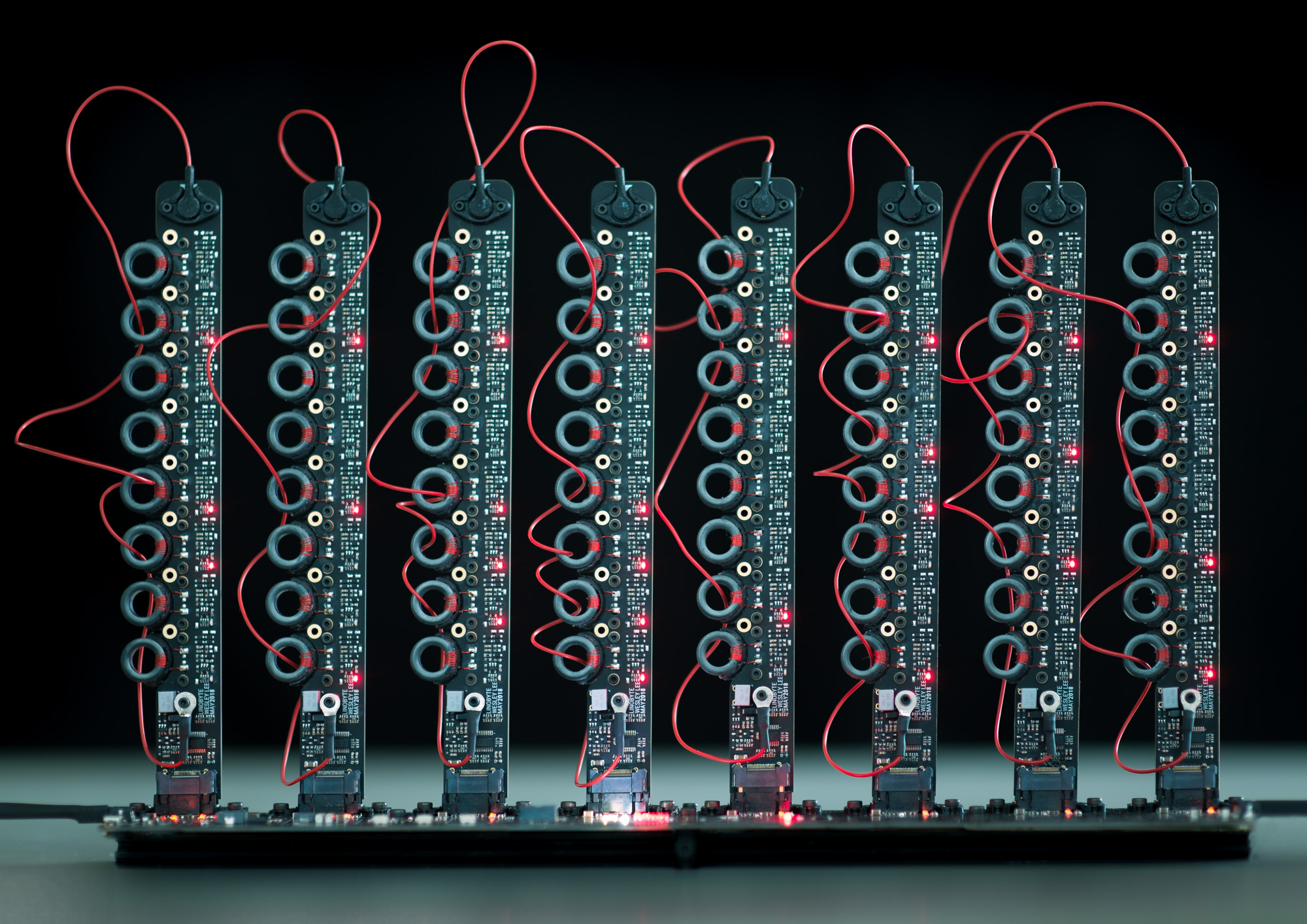
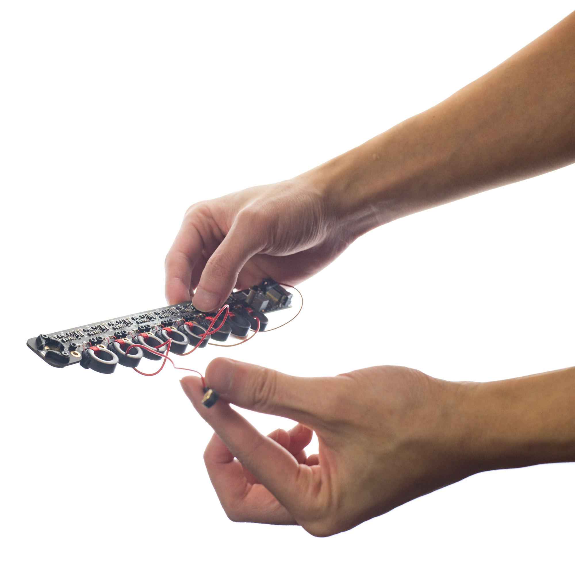
The whole process is quite straightforward, and the result is immediate: the user can write up to 8 characters - a word, in the Linobyte system. Each character consists of one eight-bit byte. Each core represents one bit, and by weaving the conductive wire through the core center, the user sets a bit as positive. By skipping the core, its set as zero. By connecting the wire to the final position, the byte is written.
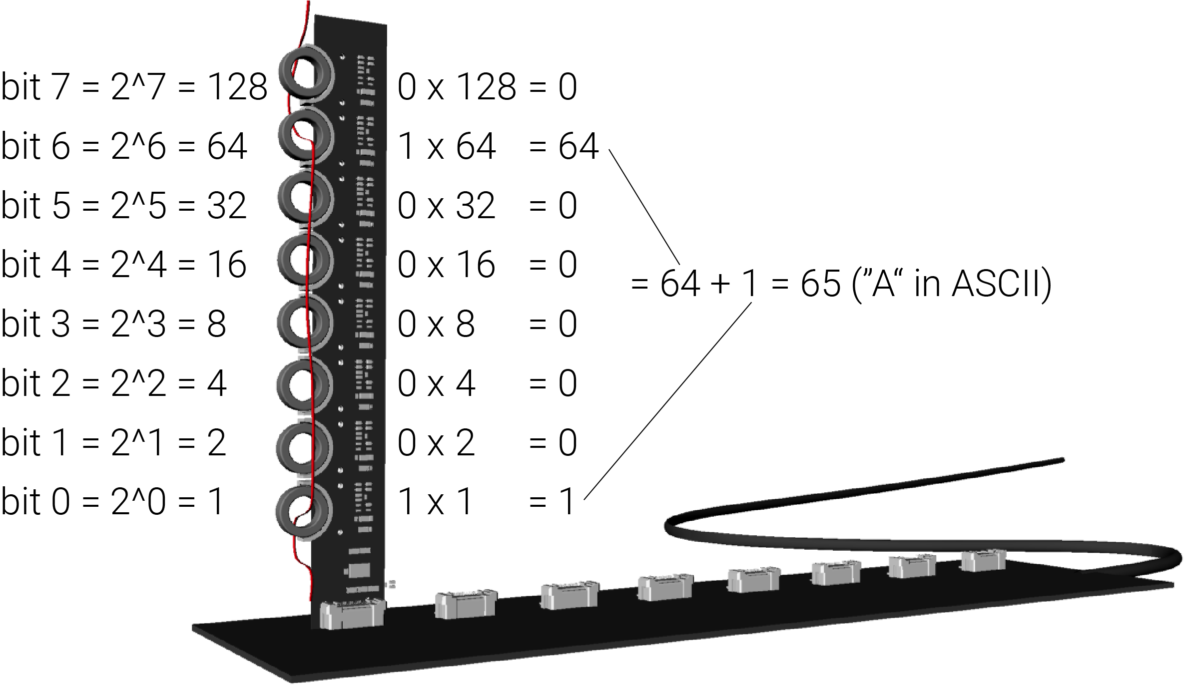
So, if the user wants to write the “A” character, the steps should be the following:
- Find out the binary value in ASCII of the “A” character by checking on the ASCII table (see image below). “A” in ASCII is 65 in decimal and 01000001 in binary.
- Figure out which bits have to be set in the “Char” board: the first bit (least significant), or bit 0. And the seventh bit, bit 6. (bits are being counted from the right to left)
- Weave a wire through the respective coils: zero and six.
- Connect the wire to the final position (will be indicated on the board)
- Check the character on a screen and correct or proceed to the next character.
ASCII table:
(I’m aware that ASCII chars only require 7 bits and not 8)

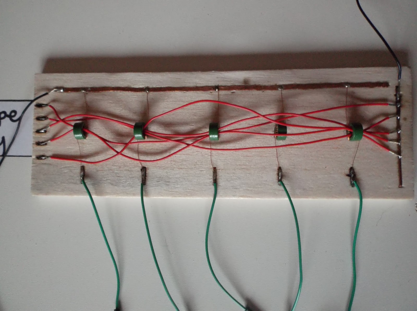
Core memory experiment from http://www.timui.org/2015/
Functional Block Diagram
Coils are out of order in the following diagram:
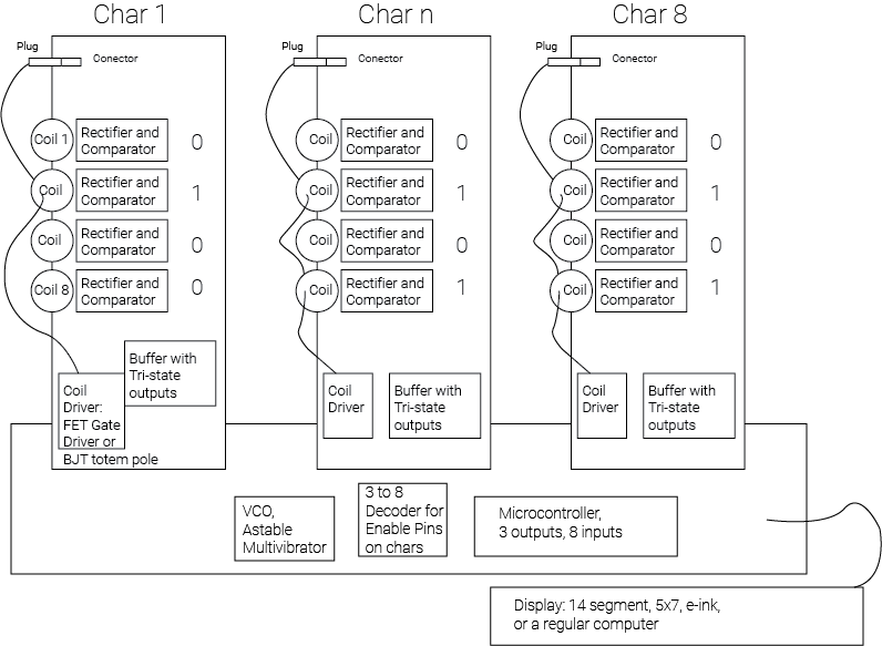
(So, basically, 1 word = 8 chars = 8 bytes = 8 * 8 bits)
Description of the main components:
Char
- Coil: a 1:10 to 1:30 transformer (the single turn will be the wire than can be weaved or not)
- Rectifier: Full bridge of schottky rectifiers: wire can be weaved from any direction
- Comparator: Since I don’t know for sure how efficient the coil transformer will be, I want to be able to set the threshold manually.
- Coil Driver: Sends pulses through the coils. A pulse rated capacitor (probably Wima MKT) will be used in series to prevent coil saturation. Square wave signal will come from main board (either a VCO, astable multivibrator or a PWM signal from the MCU).
- Buffer with tri-state outputs: Outputs will be active or high-impedance depending on Enable pin. So I can read all chars using the same pins on the MCU.
Word
- VCO/Astable Multivibrator: generate a reference frequency for the coil drives. Configurable via a trimpot. Fallback will be a PWM generated by the MCU.
- 3 to 8 Decoder: with three pins on the MCU I can enable one of the 8 chars at a time, so only one of them is driving the 8 inputs on the MCU.
- Microcontroller: will read the chars and print them out.
Display
I personally really wanted to experiment with e-ink displays (Should be doable by adding an SPI header on the main board), but 16 segment displays or 5x7 matrixes might be more thematically suited - and are quite easy to use. Another option would be having the whole system just act as a keyboard: plug it into a computer and type the text that is in the coils (Raspberry pi + a small display for example).
Power supplies (not drawn)
Microcontrollers and ICs in general will use 3.3V. I might want to power the coil drivers with 5V, 12V or 24V depending on how efficient the transformers are. I plan to power the whole thing via a USB port and have the appropriate buck and boost converters on the board. I will avoid LDOs because due to the clamp diodes to 3.3V or 5V on the rectifiers, the regulator will probably need to sink some current.
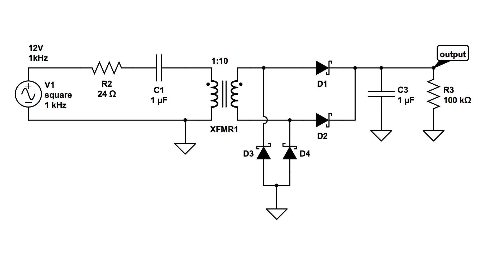
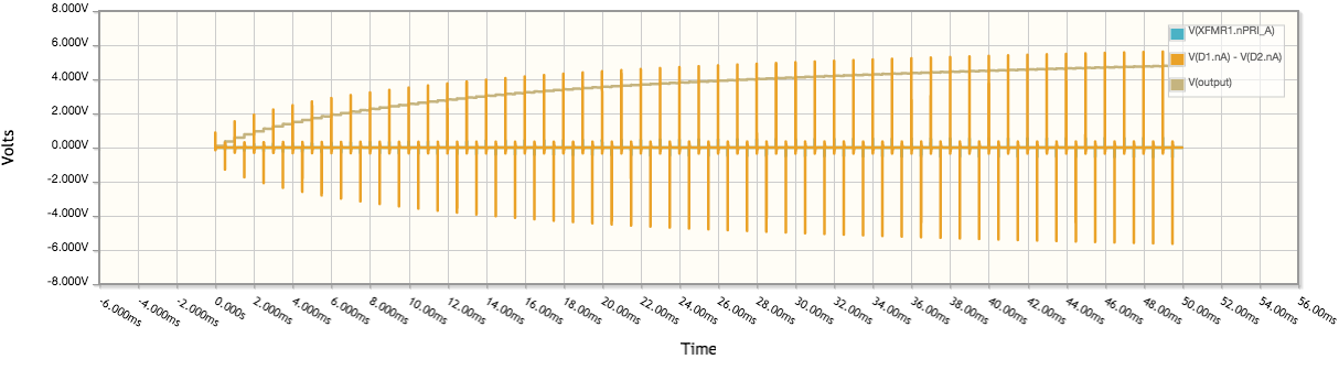
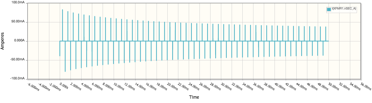
Simulations
As I designed it away from my workbench, I had to simulate some parts instead of prototyping it.
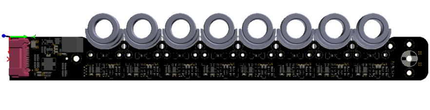
PCBs
As of 19/April.
2D view:
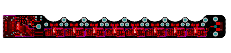
3D view:
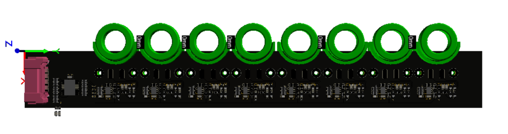
As of 10/April.
2D view:
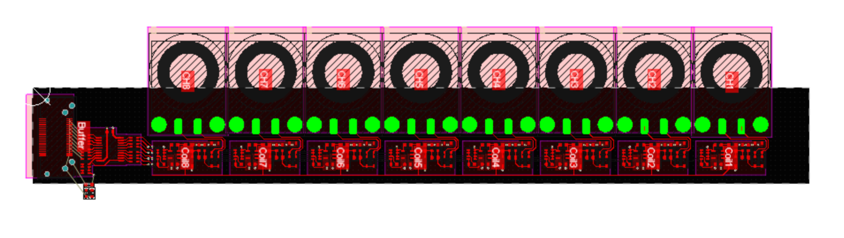
3D view:
Naming
The name is a pun with the term linotype and byte:
“Linotype, typesetting machine by which characters are cast in type metal as a complete line rather than as individual characters as on the Monotype typesetting machine.”
Encyclopaedia Britannica on “Linotype”
Refs during research
Hartmann, R. (n.d.). drhart - Core Rope Memory. [online] Drhart.ucoz.com. Available at: http://drhart.ucoz.com/index/core_memory/0-123 [Accessed Apr. 2018].
http://qrp.gr. (n.d.). Core rope memory. [online] Available at: http://qrp.gr/coreROM/ [Accessed Apr. 2018].
Ritter, T. (2002). A Magnetic Core ROM. [online] Ciphersbyritter.com. Available at: http://www.ciphersbyritter.com/MARK8/MAGCORE/MAGCORE.HTM [Accessed Apr. 2018].)
Ryals, P. (2012). Jacquard Looms and Rod ROMs. [online] Museum of Computer Culture. Available at: http://www.computerculture.org/2012/10/jacquard-looms-and-rod-roms/ [Accessed Apr. 2018].
Schlaepfer, E. (n.d.). MOnSter 6502. [online] Monster6502.com. Available at: https://monster6502.com/ [Accessed Apr. 2018].
Examples and references during design
Pcbway.com. (n.d.). 4-layer PCB standard stackup. [online] Available at: https://www.pcbway.com/multi-layer-laminated-structure.html [Accessed May 2018].
Eeweb.com. (n.d.) Edge Coupled Microstrip Impedance Calculator. [online] Available at: https://www.eeweb.com/tools/edge-coupled-microstrip-impedance [Accessed May 2018, Tw=0.25mm Ts=0.25mm]
GitHub. (2017). dmadison/LED-Segment-ASCII. [online] Available at: https://github.com/dmadison/LED-Segment-ASCII [Accessed 10 Sep. 2018].
Could Sawtooth waveform be optimal for transoformer input?
How to build a low cost current transformer
AC current sensing using current transformer
How do I design a current transformer
Maxim App note 3616, Adding extra histeresis to comparators
https://www.maximintegrated.com/en/app-notes/index.mvp/id/3616
Texas Instruments: Comparator with histeresis reference design
http://www.ti.com/lit/ug/tidu020a/tidu020a.pdf
Potential Items for Bill of Materials
Potential coils: 9mm x 16mm x 5mm (inner, outer, thickness)
Mouser
Kemet ESD - R Series
[S]chmitt Trigger Octal Non Inverting](https://www.mouser.at/ProductDetail/Nexperia/74HC7541PW118?qs=sGAEpiMZZMtOwpHsRTkso4N4DgL6o1r6unaSV%252bVDkdI%3d)
8 to 3 encoder (Auto adressing on 16 Segment Displays (shift decoded 1:8 by 1, adds 1 to 3 bit value))
Card edge 20 Pos connector
https://www.digikey.com/product-detail/en/te-connectivity-amp-connectors/5-5530843-0/A31722-ND/770548
e-ink
296x128 2.9in
https://www.amazon.de/Waveshare-Resolution-Electronic-Controller-interface/dp/B071LGVVL1/ref=sr_1_1?rps=1&ie=UTF8&qid=1523130359&sr=8-1&keywords=e+paper+arduino&refinements=p_76%3A419122031
PSA23-11SRWA (~ 300mA per char) https://www.mouser.at/ProductDetail/Kingbright/PSA23-11SRWA?qs=VdjlWU%2fzoOGQsM3wN0NEHg==
ZXGD3005 ZXGD3009